|
||||
| Figure: 1: Foto of the vision studio with motion capture setup | ||||
Optical Motion capture is the task of acquiring motion information from a moving subject that is observed with an imaging device such as a camera. The acquisition of human motion data is a prerequisite for the control of artificial characters in Virtual Reality and Augmented Reality applications, as well as in Computer Animation and Video Games. The analysis of human motion, e.g. gesture recognition, can be used for intelligent user interfaces and automatic surveillance applications.
Traditionally, optical motion capture systems rely on the use of scene-invasive equipment such as markers or special clothes. In our work, we are investigating the problem of tracking the motion of a moving person without the use of markers. In order to achieve this, tracking techniques from computer vision are combined with the reconstruction of the volume of the moving person. Our system runs at interactive frame rates.
Fig. 1 shows our vision laboratory. The person who is to be tracked moves in front of several Sony DFW-V500 IEEE1394 cameras. For this application we acquire video streams at a resolution of 320x240 pixels in color mode. The cameras are triggered externally, the maximal achievable frame rate with the external trigger is approximately 15fps. Two cameras are connected to one PC (AMD Athlon 1GHz). On the floor of the laboratory a checkerboard pattern can be seen which is used for calibration of the camera setup (We use Tsai's method for intrinsic and extrinsic calibration).
Our approach combines efficient real-time optical feature tracking with the reconstruction of the volume of a moving subject to fit a sophisticated humanoid skeleton to the video footage. The scene is observed with 4 video cameras, two connected to one PC (Athlon 1GHz). Our system consists of two parts, a distributed combined tracking and visual hull reconstruction system (online component) and a skeleton fitting application that takes recorded sequences as input. For each view, the moving person is separated from the background by a statistical background subtraction. In the initial frame, the silhouette of the person seen from the 2 front view cameras is separated into distinct regions using a Generalized Voronoi Diagram Decomposition. The locations of the hands, the head and the feet can now be identified. In the front camera view for all video frames after initialization the locations of these body parts can be tracked and their 3D location reconstructed. In addition a voxel-based approximation to the visual hull is computed for each time step.
A 2-layer kinematic skeleton is fitted to these data for each time step in a separate step. The first layer of this skeleton can be fit to the 3D locations of the 5 tracked body parts in real-time. The second layer extends the first layer by a special representation of body limbs which enables to find the correct configurations of arms and legs using the reconstructed volumetric data.
The software consists of 2 main components. The online system is implemented as a distributed client-server application. Each client runs on a separate PC and processes the video streams from 2 connected cameras. The clients precompute the visual hulls from 2 camera views, run-length-encode them and transmit them to the server. The background subtraction is also performed on the client in real-time. For the 2 front-viewing cameras the client software additionally tracks the image plane locations of the head, the hands and the feet an the reconstructs their 3D locations. Due to the flexible software architecture more cameras can be easily integrated, currently we are experimenting with setups of 6 and 8 cameras. The skeleton fitting is currently implemented as a separate application working on recorded sequences.
In the following sections the separate steps are described more thoroughly.

| ||||
| Figure: 4: Silhouette split into distinct regions by Generalized Voronoi Diagram Decomposition. Head, hand and foot regions are painted in darker gray. | ||||
In the initial frame the person is supposed to stand in an initialization position, the body upright and the arms spread to the sides at maximal extent. In order to identify the locations of the head, the hands and the feet in this initial position, the silhouette is split into distinct regions by means of a Generalized Voronoi Diagram Decomposition
A short movie showing the scene from one camera perspective can be seen here. The corresponding sequence of silhouettes is shown in this movie.
 |

|
|||

|

|
|||
| Figure: 6: Visual hulls re-projected into video frames (top) and into model of the acquisition room (bottom) | ||||

|
||||
| Figure: 7: Screen-shot of the server rendering the visual hull as 3D point set (l) and one client showing the silhouettes from the connected cameras (l). The tracked feature locations are marked by gray circles. | ||||
 |

|
|||
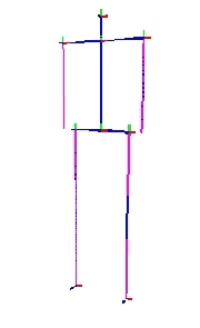
| Figure: 8.2: Skeleton layer 1 (l), Skeleton layer 2 (r) render into a virtual model of the acquisition room | ||||
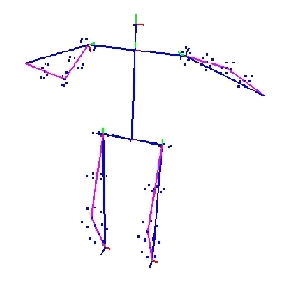
The human body is modeled as a 2-layer kinematic skeleton. The first layer consists of 10 bones connected to a hierarchical structure by intermediate joints. On layer 1 the arms and legs are only represented by 1 segment each, elbow and knee joints are not modeled. Skeleton layer 2 extends layer 1 by a special representation of arm and leg segments. The volumetric extent of the extremities is modeled by volume samples attached to the skeleton bones. By knowledge of the skeleton dimensions and the length of the layer 1 segment at each time step, the elbow and knee angles are fully determined. This construction extends the layer 1 structure by only 4 additional rotational degrees of freedom around the layer 1 arm and leg segments.
Fitting the skeleton to the visual hull data is a 2-step process. The layer 1 skeleton can be fitted to the 3D locations of head, hand and feet at almost no cost. The additional degrees of freedom on layer 2 can be found by searching for a best correlation match between the reconstructed volume data and the volume samples attached to the extremities.
Recent extensions of the method and a more detailed description of the multi-layer skeleton fitting can be found here.
 |

|
|||
| Figure: 9.1: 2 example frames with skeleton layer 2 fitted to the current motion state of the person. The red spheres mark the 3D locations of tracked body parts. | ||||

|

|
|||

|

|
|||
| Figure: 9.2: Skeleton layer-2 fitted to example visual hull. The results are rendered into a model of the acquisition room. | ||||
Experiments with the system prove our combined approach to be reliable even against strong visual hull reconstruction errors. This makes our method particularly suitable for setups with only few cameras. Detailed descriptions of experimental results can be found in Sect. Publications.
The following movies show results obtained with our system :
movie1
movie2
movie3
movie3
Results with the extended multi-layer skeleton fitting can be found here.